Fieldbus Modules | Networking: The backbone of the automation solution
Source: Bachmann System Overview catalog | Bachmann electronics GmbH www.bachmann.info.
As an automation specialist in the area of distributed energy generation plants, Bachmann electronic GmbH know the significance of a powerful, scalable and absolutely reliable networking solution. Netwokring as the backbone of every automation solution has the task of connecting different sub-components according to their requirements in terms of signaling. In this regard, rigorous requirements are imposted on real-time capability, protection against tampering and availability.
To meet these different high requirements, Bachmann electronic provides an extensive offering of different networking components. For eaxample, their offering enables a central control room connection adapted to the particular customer requirements via Ethernet or a machine-internal, flexible connection of the individual machine components on the controller via real-time capable fieldbuses. You decide which of the networking possiblities established on the market best fits your automation task. In this regard, the transmission medium, optical fiber or copper can be freely selected in the accordance with the requirements imposted on the resistance to the interference and distance. Bachmann electronic is guaranteed to have a suitable solution in its product line.
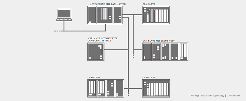
CANopen | Proven millions of times over
The Controller Area Network (CAN) in the CANopen specification has now developed to become the leading fieldbus system for industrial automation. Proven millions of times over and perfectly mature, it offers the ideal basis for safe, easy and yet flexible networking tasks. By using only one fieldbus, the compact CAN I /O modules from Bachmann electronic facilitate the homogeneous design of an automation system with high efficiency and packing density. Galvanic separation from the main station, the scalable range and the extremely low-cost wiring make the modules particularly attractive for the users.
Fold out to read more about the CANopen module available:
CANopen Master Module CM202
The CAN master module CM202 can operate either one or two separated networks. Both connections can be configured independently as NMT master or slave. In an M1 controller up to four CANopen master modules CM202 can be operated.
- Up to 4 CANopen master modules per M1 controller
- 2 independent CAN buses per CANopen master module
- Can be used as NMT master or slave
- Transfer rate 10 Kbaud to 1 Mbaud
- Bus length to 5000 m (signal repeater required)
- Galvanic isolation
- Short circuit proof
See specifications for item:
Available accessories for CM202:
Terminal 03-pin grid
Cable CAN
PROFIBUS | Widely used, esteemed everywhere
PROFIBUS is a field bus that is widely used, particularly in the area of mechanical engineering and plant engineering and even today – in spite of all Ethernetbased fieldbuses, it continues to show increasing quantities. A broad palette of peripheral components and an active user organization will also ensure long-term availability of PROFIBUS components in the future. Bachmann electronic offers a fieldbus interface module for the backplane that can be used both as master, as well as slave. The Bachmann SolutionCenter contains a complete configurator that enables interfaces to the engineering tools of other manufacturers through the consistent application of standards.
Fold out to read more about the PROFIBUS module available:
PROFIBUS DP Master Module DPM200
The interface module for Profibus DP (Distributed Peripherals) can be operated as DP master, DP slave or as combined master/slave, which in a multi-master network offers variables for another master. The process data is available to the application program as logical I/O module and thus can be reached via the process image or via the function interface.
- Up to 3 DPM200 modules per M1 controller
- Transfer rate 9.6 Kbaud to 12 Mbaud
- 8 kByte shared memory for process data image
- Consistency lock for data blocks is configurable
- Two internal bridged connections for loop-through of the cable
- Galvanic isolation between fieldbus and controller
See specifications for item:
DeviceNet | Proven basis, new view
DeviceNet is based on the same physical layer as CAN. However, it has an object-oriented view of the process data and uses monitored point-to-point connections. The bus system is standardized through the ODVA (Open DeviceNet Vendor Association). The DeviceNet master module and its software equipment enable operation of the M1 controller as DeviceNet master and DeviceNet slave, as well as simultaneous operation in two networks in combined master/slave mode. The cyclic data is available to the application program via the process image. Acyclic accesses and status commands are possible via libraries for M-PLC and C/C++. The configuration is executed via the Bachmann SolutionCenter.
Fold out to read more about the DeviceNet module available:
DeviceNet Master DNM201
The DNM201 fieldbus master module allows the M1 controller to be used as bus master in DeviceNet networks. The DNM201 module is used to connect drives and input /output interfaces. The system bus of an M1 supports up to 8 separate networks, each with a maximum of 64 nodes that can be operated with different cycle times. Thus the bus architecture allows up to 512 DeviceNet stations (nodes) to be controlled individually.
- 1 DeviceNet module for up to 64 nodes
- 8 separate networks with max. 512 nodes (requires 8 DNM201 modules in one M1 system)
- Support of »Multi-Master« mode
- 5-pin connector (in acc. with open DeviceNet standard)
- Isolation voltage from DNM201 to case 100 V
- Isolation voltage from DeviceNet bus to system voltages of the controller 500 V
- Baud rates 125/250/500 kbit / s
- Extensive status LEDs
- Modes: Master (multi-master capable), slave, master / slave
- Module and network status LEDs (MS/NS)
- Error detection: Duplicate MAC-ID check, device heartbeat, device shutdown message
- Automatic resumption of communication after failure
See specifications for item:
Available accessories for DNM201:
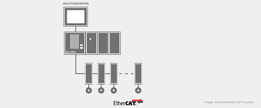
EtherCAT® | The Universal drive bus
The EtherCAT® bus system is ideally suited for controlling servo-electric drives by an M1 controller. The Bachmann SolutionCenter contains convenient tools for the configuration, commissioning and diagnosis of the network. In combination with the Drive Middleware, the project planning of applications with drives of different manufacturers is also very easy.
Fold out to read more about the EtherCAT® module available:
EtherCAT® Slave Module ECS200
The ECS200 allows connecting a M1 controller system as slave device to an external EtherCAT® network. The goal is to use the M1 to control an autonomous intelligent subsystem within a complex system or machine. The application programs (PLC, C/ C++) have full access to the incoming and outgoing cyclic process data via the MIO and SVI interfaces and via the process image. The slave state and the connection state can be recognized by the user programs. Thus, emergency situations like network problems or failures of the external EtherCAT® Master can be handled individually in dedicated emergency routines. The application programs at the slave station can be accurately synchronized to the external EtherCAT® bus for closed-loop control operations. The execution cycle of the user programs can be maintained also in emergency situations. Distributed Clocks are supported. Amount and size of the incoming and outgoing cyclic data are configured on the slave station, and then a dedicated ESI file is generated to configure the master system. The PDO mapping can be defined statically or can be created by the EC Master dynamically. As EtherCAT® slave, the M1 is a module device with a static object dictionary that does not need to be further configured by the master. Diagnostic is supported by several LED indications on the module, by log messages and by a monitor in the Bachmann SolutionCenter.
- 2 EtherCAT® Ports IN, OUT
- Max. 700 Bytes cyclic data for Rx und Tx each
- Bus interval 125 μs to 10 ms
- Distributed Clock
- User programs can be synchronised to EtherCAT®
- Connection- and network state visible for user programs
- Behavior in case of network problems confi gurable
- LED for display of slave state
- Error-LEDs for In- and Out-Port
- Galvanic isolation from the system
- Condensation-proof ColdClimate design on request
See specifications for item:
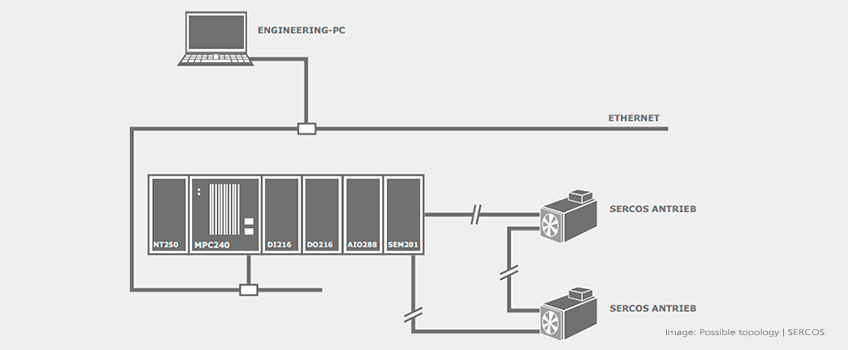
SERCOS | Specialised for rigorous requirements
SERCOS (SErial Realtime COmmunication System) is a dedicated bus system for activation of high-quality electric drives and servo amplifiers. Communication is configured on the controller and distributed to the drives when the system boots. The process data of the drive is available in standardised form and makes not only the numeric values available via appropriate services, but it also makes meta information, such as symbolic names, input limits and units, available. Via service channel accesses, in addition to the cyclic process data, acyclic parameters at runtime from the application program can also be changed or transferred from a list of initial parameters at system start.
Fold out to read more about the SERCOS module available:
SERCOS Master Module SEM201
The SERCOS (Serial Real-time Communication System) master module SEM201 is capable of controlling up to 32 drives. The bus has a ring structure and offers a high level of interference immunity thanks to the fibre optic technology.
- SERCOS 2 Standard IEC 61491
- Fiber optic technology
- Bus with ring structure
- 2 Kb x 32 DPRAM
- Transfer rates: 2/4/8/16 Mbaud
- Cycle times: 62.5 µs to 65 ms
- Multiple masters can be synchronised
See specifications for item:
M-BUS | Standardised basis, integrated solution
Energy meters (gas, heat, output, water etc.) are required in power plants, and in combined heat and power generation in particular, for regulation, as well as accounting. The M-Bus standardised in EN 61334-4-1 is highly prevalent in Europe for the connection of these meters. The OSI model, if M-Bus is the physical layer, the data link according to IEC 870 and the application layer according to EN 1434-3 are specified for this protocol. An integrated solution is provided by a rugged and easily installable M-Bus adapter and its convenient integration as a fieldbus in software communication.
Fold out to read more about the M-BUS module available:
MBUS201 Master
The MBUS201 master enables easy connection of a serial RS232 interface on M-Bus via an adapter. The M-Bus is a widely used fieldbus in accordance with EN 13757 for reading out consumption data from meters (electricity, water, gas, heat). Transmission is serial via voltage and current modulation on a twowire line that is protected against polarity reversal. The M-Bus protocol is integrated as an intuitively configurable fieldbus, and is addressed via the UFB (Unified FieldBus ) software interface.
- Max. 4 MBUS201 masters per M1 controller
- M-Bus protocol implemented as fieldbus
- Max. 5 meters (slaves) per master
- Adapter can be inserted directly on the DSUB connector
- Integrated M-Bus power supply
- Interfaces M-Bus and RS232 are galvanic isolated
- LED display for collision detection and power supply
- Data transmission at 300 to 9600 bps